Setup Menu
The F-900 has a number of utility functions that allow the user to manage the instrument’s capabilities. These functions are accessed by pressing the right arrow when Setup is highlighted on the Main Menu. The setup utility options are: Measure, Autosave, Sensor, Calibration, Time, Flow, Chamber, Terminals, and Board. Use the up or down arrow to select the desired option and then press the right arrow to enter the choice. Press the left arrow to exit to the Main Menu.

Setup Measure
The Setup>Measure menu allows the user to setup a measurement in 1 of 2 different modes: Monitor Mode or GC Emulation Mode. Instructions to use Monitor Mode are found on page 2. GC Emulation Mode is available with the F-900 Research Kit and requires the use of the inline injection port with septum. To save changes in the Setup>Measure menu, press Save. Use the up and down arrows to toggle between options.
Setup Autosave
To select the Autosave feature, press the right arrow key when Autosave is highlighted. This allows the user to setup the instrument to automatically store measurements, and to start a new measurement without explicitly saving the old one. This mode is convenient when taking fast, repetitive measurements, as well as when it is not necessary to review each measurement immediately after taking it. The files created by the F-900 are saved in .csv (comma separated value) format, to be opened with Microsoft Excel or other spreadsheet program.
In the Setup>Autosave menu, the top line of the display will read enter and save and the directional arrows. Next to Autosave and Yes or No indicating whether this feature is turned on or off. Below Autosave is the Interval option where the user can set the time interval. This is the length of time in seconds between saves, when the autosave feature is selected. The default autosave interval is 10 seconds.

- To set the instrument up to automatically store measurements press the right arrow key to highlight the word no on the display, then press the up/down arrow to switch to yes. Press the Save key to save the configuration. After saving, it will exit to the Setup Menu.
- To set the instrument up to not automatically save measurements, toggle the up/down arrow key until no is on the display, then press the Save key to save the configuration. To save data when Autosave is disabled, press the “Save button during the measurement.
- When Autosave is highlighted, press the up/down arrow to get to the Interval line and then use the right arrow key to highlight the time interval value. Press the up/down arrow key to change the time interval. Press Save to save changes.
- To avoid changing any configuration, press the Stop key to exit back to the Setup Menu.
Setup Sensor
The Setup>Sensor menu has Sensor Selection. Sensor Selection allows the user to turn on/off the different sensors of the F-900. After selecting any of the menu options from the Setup>Sensor menu, the display will prompt “Are you sure you want to continue?” Press Enter to continue to the selection.
Not all F-900’s are built with all sensors, so see the Production Check Sheet at the end of the manual to see which sensors are included in your unit. All units are equipped with a High Resolution C₂H₄, ethylene sensor (PPB) and an extended range C₂H₄, ethylene sensor (PPM). The C₂H₄ PPB measures from 0-4 ppm. The C₂H₄ PPM measures from 4-200 ppm, with a lower detection limit of 0.5 ppm. Optional sensors available for carbon dioxide are the PPM or the PCT, which gives values in percent (%). There is also an additional sensor available for O₂ (percent oxygen). The optional sensors are in series, meaning the gas sample will flow to the CO₂ PPM, then CO₂ PCT sensor, then O₂ sensor. The C₂H₄ sensors are parallel, meaning a valve changes the gas flow between the C₂H₄ sensors, again depending on the current concentration.
Sensor Selection: Press the right arrow when Sensor Selection is highlighted to see the list of sensors.
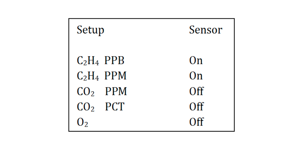
- Use the up/down arrows to select the sensor to adjust and then the left/right arrow keys to switch between columns. Once in the column with the On/Off, use the up/down arrow to turn the sensor On/Off.
- Both ethylene sensors should always be turned “On” for measurements. The firmware will control which ethylene sensor is used to measure the gas sample.
- If sensors are not included in your instrument, please set them to “Off”.
- If not actively using the CO₂ PPM sensor, set it to “Off” to conserve battery life.
- Press Save to save any changes.
- Press Stop to exit to the Setup Menu.
Setup Calibration
Current Calibration Parameters and re-calibration steps for C₂H₄, CO₂, and O₂ sensors can be found in the Calibration Menu. Press Enter to confirm and get into the menu. The options at the Setup>Calibration menu are C₂H₄, CO₂, O₂, system DAC flow and injection parameters.
C₂H₄ Calibration
Re-calibration or changes to any of the Calibration Parameters for C₂H₄ should be performed under the supervision of a Felix Instruments technician only.
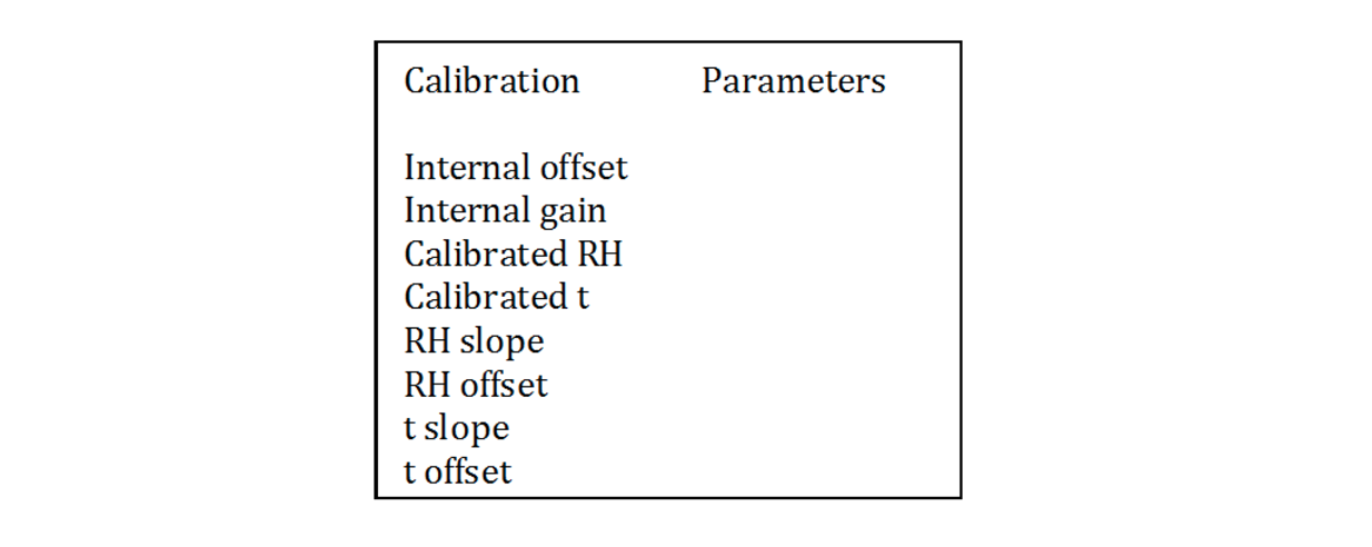
The options from the C₂H₄ Calibration menu are for the C₂H₄ PPM sensor, C₂H₄ PPB, offset autocorrection or sensitivity correction. Calibration Parameters are set by a Felix Instruments technician during factory calibration and are specific to each instrument. The internal offset is the ADC voltage output from the sensor when no ethylene is present, and gain describes the linear increase in the ADC voltage output from the sensor in the presence of ethylene. The RH, T slope and offset are applied to the ADC voltage to correct for shifts in relative humidity and temperature that may occur during the sample period. the temperature and RH parameters are automatically populated during ppb sensor span.
The ethylene sensor calibration will drift over time. Occasional recalibration of the sensors can be carried out using calibration gas in the range of each ethylene sensor. For example, 1 ppm C₂H₄ gas can be used to adjust the internal gain reading for the C₂H₄ PPB sensor. To adjust the internal gain of the C₂H₄ PPM sensor, standard gas between 5-100 ppm could be used. The timeframe for adjusting the gain depends on the specific sensor and its use. The C₂H₄ PPB sensor may require weekly gain adjustments, while the C₂H₄ PPM sensor may require gain adjustments every 6 months.
Offset Autocorrection
Offset autocorrection allows the unit to adjust the baseline, or zero, for the ethylene sensors, which may drift from the zero set at the time of calibration. The offset autocorrection procedure typically takes about 25-30 minutes and takes place during “Sensor Stability”, the first screen when measurement mode is initiated. The default interval between offset autocorrections is 24 hours for continuous use, or during the next start-up for units that are not running continuously. If the unit is exposed to concentrations greater than 200 ppm during the measurement period, the offset autocorrection will be initiated the next time the user enters “Sensor Stability”, even if less than 24 hours have passed. The offset autocorrection relies on there being KMnO4 in Chamber Out.
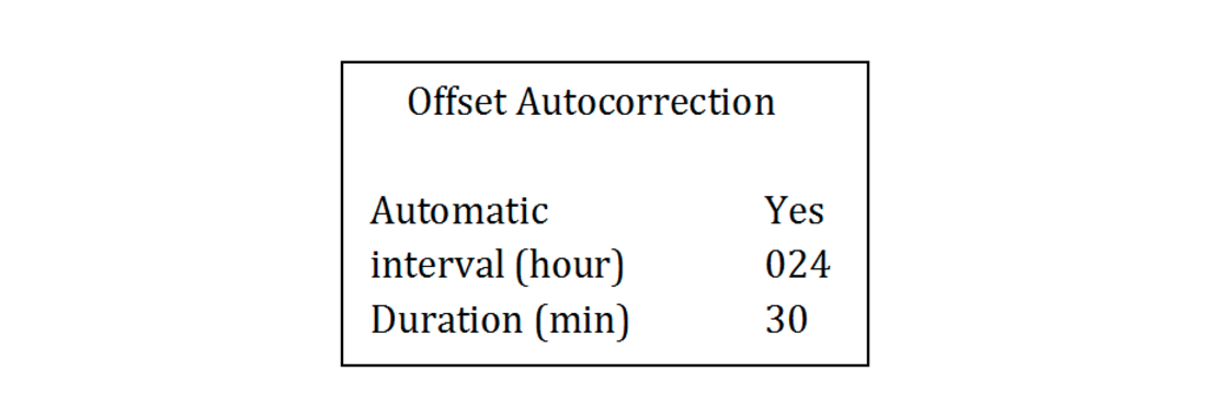
Automatic: If “Yes” is selected, the unit will automatically adjust the offset every 24 hours or upon startup if more than 24 hours have passed between uses. The offset will be corrected when the user first enters measurement mode and is in the “Sensor Stability” screen. To enable the automatic offset adjustment, and to ensure that the latest offset adjustment so that the unit is using the most recent zero, change the “Automatic” line to “Yes”.
Interval: The offset autocorrection interval can be changed from 24 hours (default) to any user selected interval in hours.
Duration: The amount of time the offset correction lasts. It is recommended to have it between 15-30 minutes.
C₂H₄ PPB Re-Calibration
Please refer to section “F-900 On-Device Calibration” on pg 36
CO₂ Calibration
Always perform a zero calibration of the sensor before setting the span.
To access the Calibrate CO₂ feature of the F-900, navigate to Setup > Calibration > CO₂. Press Enter to continue to the Calibration mode. Select the CO₂ sensor to be calibrated (PPM or PCT).
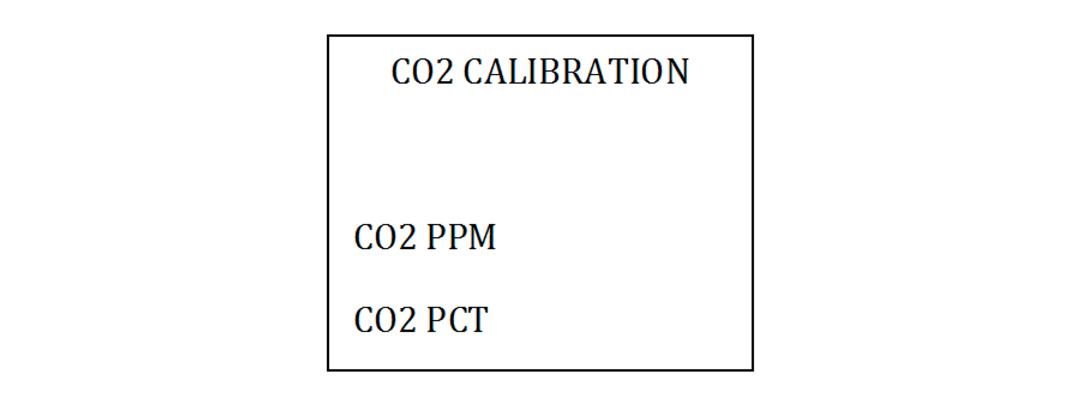
The CO₂ sensor needs to be enabled in the Setup>Sensor>Sensor Selection menu to access the Setup>Calibration>CO₂ menu. The recommended standards to use for the CO₂ sensors can be found on Table 1 on pg 30.
Calibration Parameters will display the coefficients from the previous calibration.
Re-calibration allows the user to re-calibrate the sensor, setting a new zero and span for the selected sensor. CO₂ PPM zero calibration is recommended weekly. CO₂ PCT zero calibration is recommended every six months. However, if the unit is in an environment where the temperature fluctuates frequently, zero calibration may be necessary more often than the recommended intervals. Alternatively, a CO₂ scrubber such as soda lime can be placed in Chamber Out.
Turn the ethylene sensors on for the CO₂ calibration. Directions for using a buffer system in place of a standard gas may be found at the end of the section.
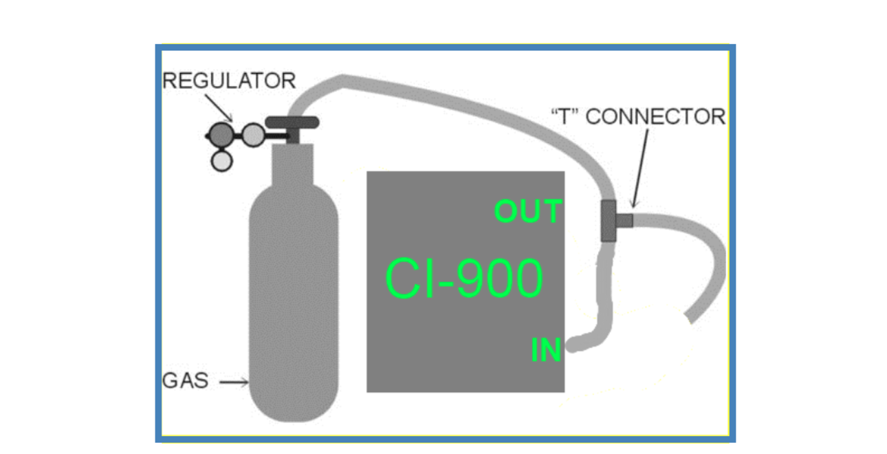
Figure 19: Calibrating the CO₂ sensor using standardized gas.
The CO₂ PPM zero calibration will drift with time and temperature therefore weekly zero calibration is recommended for the CO₂ PPM sensor. If performing the CO₂ span calibration, it should be carried out immediately after the CO₂ zero calibration. The span calibration is required every 6 months. The CO₂ span or gain calibration does NOT need to be performed every time the CO₂ zero is set.
Calibrating the CO₂ sensor with standardized gas is fairly simple and takes 20-30 minutes. Remember, to always use a "T" connection to vent excess gas and prevent damage to the internal components.
- Go to Setup>Calibration, press Enter, then select CO₂. Select the CO₂ sensor to calibrate.
- Go to Re-calibration and press the right arrow. You will hear the valves open and the pump begin to run.
The display will read Setup N₂ and press Enter. If you have pure N₂ gas (0 ppm CO₂), connect it to the inlet of the device. Be sure to have a “T” in the line so that the instrument and seals are not over pressurized. Use the regulator on the gas tank to set the flow to about 1 PSI. This will ensure the unit is provided with a bit more than the necessary gas for it to operate at 80 ml/min (wasting calibration gas will happen at over 2 PSI).
If N₂ gas is not accessible, use the Soda Lime provided with the research kit. Create a 0 ppm CO₂ environment by filling the external conditioning tube with soda lime and connecting it to the inlet. This will generate CO₂ free air, allowing the instrument to set the zero as it would with the N₂ gas.
Once the N₂ gas or soda lime is connected, press Enter. The instrument will enter a screen that reads “Internal Offset” and count down from 99.
- When the offset is obtained, the instrument will pause and allow you to calibrate to either the 20% range or 100% range. For example, if you need the instrument to read 50%, press “Save” to calibrate to the 100% range.
- In the Setup Gas screen, connect the CO₂ (use a “T” connection to not over pressurize the instrument) and change the value to 00050 %. Press “Save”.
- The instrument will now set the internal gain and count down from about 46.
- The final calibration values will then be displayed. Press “Save” to save the values, completing the calibration and returning to the Calibration Menu.
If access to standardized CO₂ gas is limited, ambient air can be used to calibrate the CO₂ span. Ambient air should only be used if a buffer tank system is implemented. The buffer tank system will help stabilize fluctuations in CO₂ levels, providing an ambient air with approximately 400 ppm CO₂ (depending on proximity to urbanized areas).
Tips for Calibrating the F-900 CO₂ Sensor with a buffer system:
- The operator should stand away from the F-900.
- Use extra tubing to get the intake source away from human breath.
- Use a buffer tank system to stabilize the intake source.
CO₂ Span Buffer Tank System Instructions
- Find and clean an empty bottle with cap, which is at least 3L in volume.
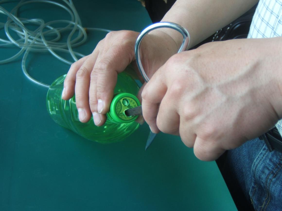
Drill two small holes in the cap of the buffer bottle: 1 hole is for the intake tube and 1 hole is for the out tubing.
Insert a short plastic tube into the cap of the buffer bottle for the “out”.
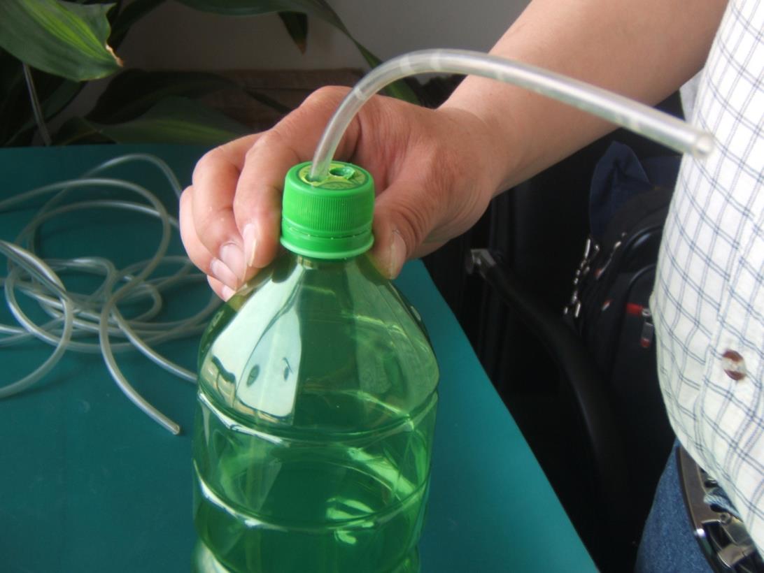
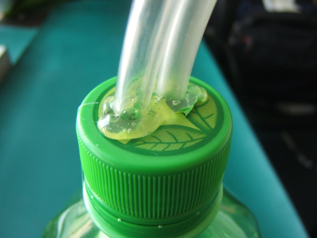
Insert a longer plastic tube into the cap of the buffer bottle that will connect to the “IN” of the instrument. Use hot glue or otherwise seal the tubing to the cap, with no leaks.
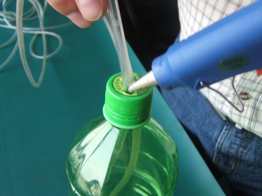
Make sure that the tube and cap has no leaks.
Connect the “in” tubing to the intake port on the instrument.
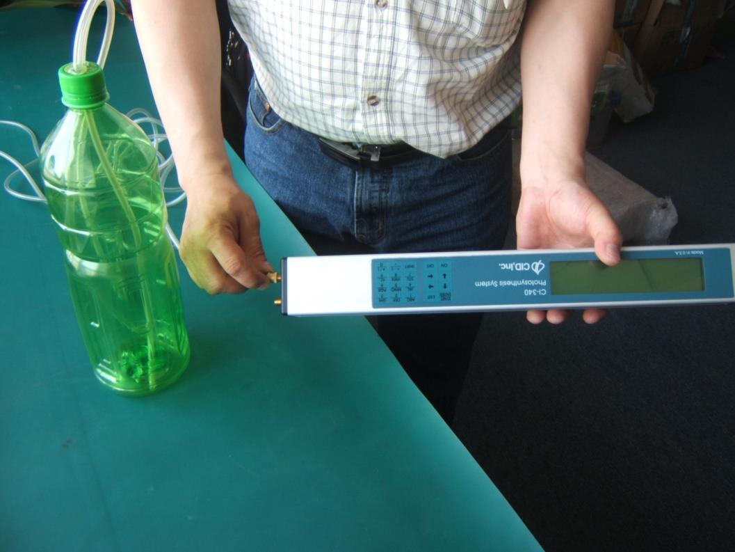
To use the buffer bottle, make sure that the tubing is clear from obstruction. Connect the In tubing to the unit. Place the buffer bottle in a location that has stable CO₂ concentration (away from operator, cars, furnace, photosynthesizing plants). Here, ambient air CO₂ levels should be approximately 400 ppm.
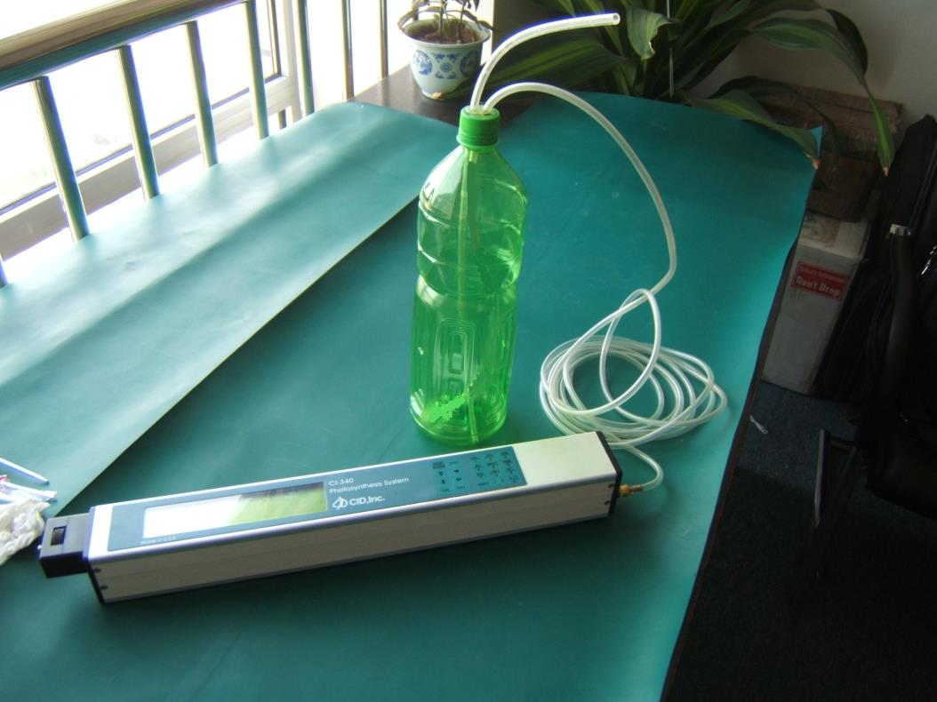
Note: The instrument shown in these images is a CI-340 Photosynthesis Analyzer (CID Bio-Science, Inc). The buffer tank system technique can be used to help stabilize the ambient intake of any IRGA CO₂ sensor (images courtesy of ZealQuest, China).
O₂ Calibration
It is recommended to use the F-900 Controller software for automated calibration of the F-900 O₂ span, but a manual calibration is possible Always perform a zero calibration of the sensor before setting the span.
The offset and gain from the previous calibration can be seen under Calibration Parameters. These values are achieved by setting a zero and a span for the unit. To re-calibrate, pressurized N₂ gas and O₂ gas will be needed. If O₂ gas is not available, ambient air may be used. If the environment changes frequently, re-calibration may be required more often than specified in the calibration schedule. To set the zero of the O₂ sensor, follow the same instructions for the CO₂ sensor zero calibration, with the following changes:
Use 0 ppm O₂ gas.
Highlight O₂ in the Measure>Settings menu and press Enter twice when it is time to set the zero.
Calibrating the O₂ sensor with standardized gas is fairly simple. Remember, to always use a "T" connection to vent excess gas and prevent damage to the internal components.
Go to Calibration, press Enter, then O₂.
Go to Re-calibration and press the right arrow. You will hear the valves open and the pump begin to run.
Use pressurized N₂ to create zero O₂ gas. When the gas is flowing and connected to the unit, press Enter.
The unit will count down as it sets the zero for the O₂ sensor. The humidity, Temperature, and Flow are displayed. The flow should continue to read 80 mL throughout the calibration- if it does not you may have a leak or obstructed tube. (Pressing Enter at any time will move you into the next step. Only do so if you want to use the previous zero calibration).
Setup Calibration gas: Enter the percent concentration, where 1000 E-3 = 100% and 210 E-3= 21%. Use the left/right arrow keys to switch between placeholders, and the up/down arrows to change the values.
Press Save to initiate the calibration.
The unit will count down from 19 as it sets the span for the O₂ sensor. (Pressing Enter at any time will move you into the next step. Only do so if you want to use the previous span calibration).
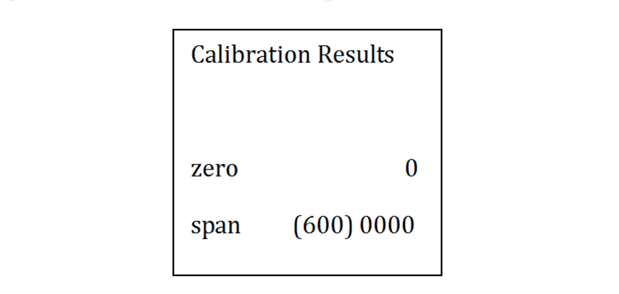
After the unit has set the zero and the span for the O₂ sensor, the Calibration Results are displayed. Press Save to save the values and return to the Calibration Menu.
Flow Rate Calibration
To calibrate the flow rate on the F-900, a separate flow meter is required. The external flow meter should work with gas and a range including 100-250 ml per minute.
Go to Setup> Calibration> Flow
Connect Hi-res flow meter to device outlet
Use up/down key to adjust flow calibration points: 100ml/min then press enter
Connect Lo-res flow meter to device outlet
Use up/down key to adjust flow calibration points: 200, 250 ml/min
Press enter after that until done (skip points 300,400 ml/min …)
Go to Setup > Flow to verify the flow at 100 and 200 ml/min
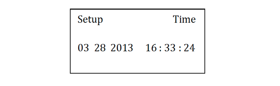
Setup Time and Date
To change the time and date on the F-900, press the right arrow when “Time” is highlighted on the Setup Menu. This utility allows the user to set-up the instrument in different time zones or to adjust the time after daylight savings.
- To change the time on the instrument, use the up/down arrows to change the values. Use the left/right arrow to highlight the appropriate column. Then, make the appropriate shift in time and press Save.
Setup Flow
The air flow of the F-900 is an important factor for taking good measurements. The default flow rate is 80 ml/min. Flow rate is adjustable from 80-250 ml/min.
A flow value below 80 ml/min can negatively impact sensor functionality. If measuring bottled gas, a lower flow rate may be used in order to reduce gas waste. If measuring open air, a higher flow rate (~300 ml/min) is acceptable. The default flow rate is 80 ml/min.
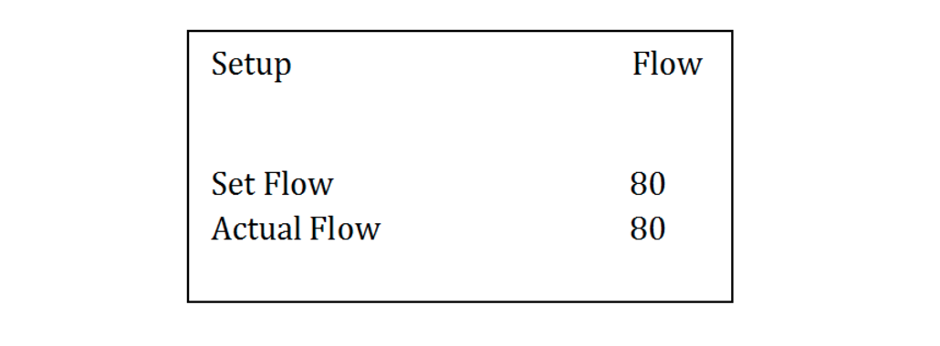
To make adjustments:
Go to Setup>Flow and press the right arrow.
Use the up/down arrows to adjust the value.
The Set Flow value is found in ml/min to the far right.
The Actual Flow value will change to match the set flow.
Press Save to save changes and exit back to the Setup Menu.
Press Stop to exit back to the Setup Menu without saving.
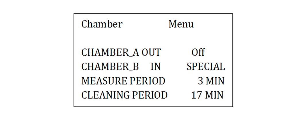
Setup Chamber
The Setup>Chamber menu allows you to turn on/off the in-line conditioning columns on the back of the instrument. The settings in Setup>Chamber are the default settings to be used to start a measurement. Once a measurement is in process, conditioning chambers can be turned on/off in the Measurement>Settings menu. If the measurement is started with PolarCept enabled, the measurement must be stopped to make changes to Chamber In at the Setup > Chamber menu.
The removable plastic containers are used to hold the consumables potassium permanganate, distilled water, soda lime, and silica gel. Keep the plastic containers on the F-900, even when empty, to protect the brass intakes. Always ensure the conditioning chamber is seated properly when screwing it on the F-900.
The purpose of the inbound chamber, Chamber In is to condition the air before it reaches the sensor. Chamber In additionally provides a “special mode” where distilled water is used to filter out alcohols before the electrochemical sensor. The use of distilled water in the Chamber In is referred to as PolarCept. It is recommended to use PolarCept (Chamber In: Special) for most ethylene measurements. PolarCept is intended for distilled or deionized water only.
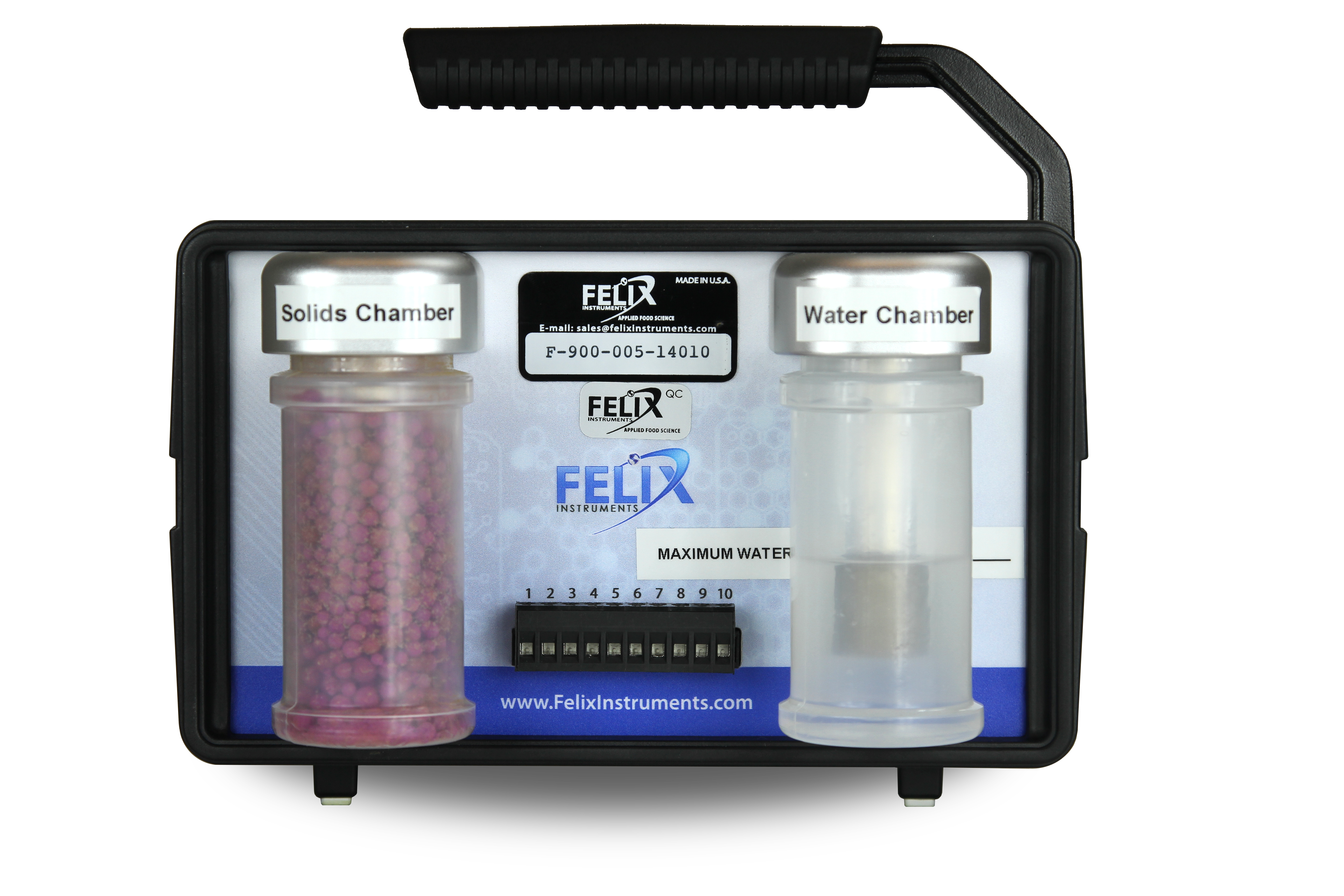
Figure 20: Solids Chamber and Water Chamber on back of instrument.
Chamber Out is on the left of the back panel. Chamber Out is the last chamber before the gas OUT port. If the outlet gas stream is connected to the field kit chamber or to the inlet of the unit, it can be used to condition the incoming gas after it leaves the sensor. Chamber Out is used with potassium permanganate (KMnO₄) for zero calibration of ethylene sensors.
Alternatively, Chamber Out could be used with soda lime to remove CO₂ from the gas stream. Similarly, silica gel is used to scrub water from air and create a 0% relative humidity gas. Most commonly, potassium permanganate is used to for zero calibration of the ethylene sensor. KMnO₄ beads (not dust) should be sourced locally by the user.
KMnO₄ has an added color indicator that turns from purple to brown when it expires and needs replacement. The silica gel from blue to pink when replacement is necessary.
To use Chamber Out to condition the air replenishing the fruit chamber, enable Chamber Out in the Setup>Chamber menu and fill Chamber Out with the appropriate consumable. Connect the fruit chamber hoses to both the IN and OUT ports on the front of the F-900.
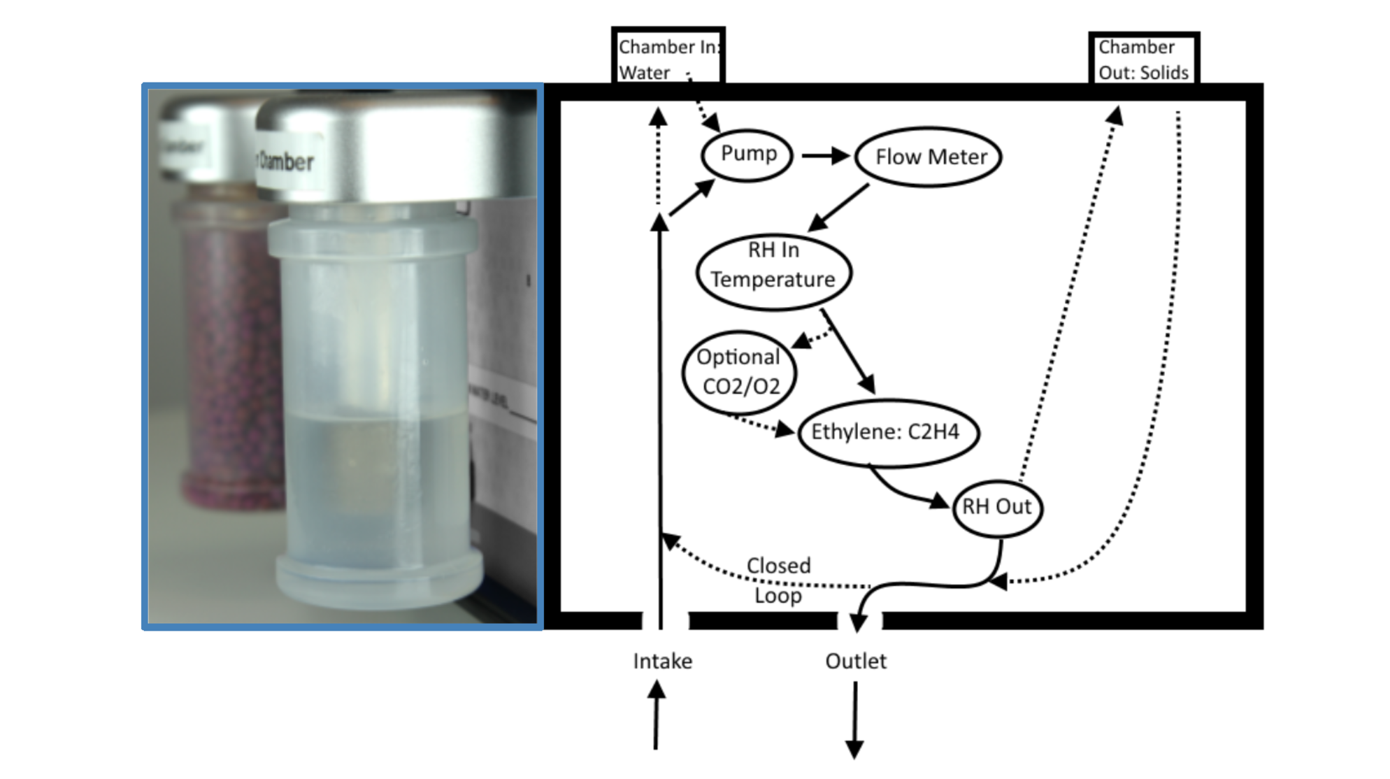
Figure 21: The back of the F-900 with removable and refillable containers for distilled water and KMnO₄ (left) and a diagram showing the flow path of the gas stream (right).
Chamber In is on the right side of the back panel. This chamber can be enabled in 2 different modes. For PolarCept, Chamber In should be filled with distilled water to help filter out interfering gases in the air stream. By passing the gas sample through the water, polar molecules are trapped or filtered from the airstream. Using Chamber In with distilled water as a filter can help reduce the interference measured when alcohol or other light polar molecules (known interfering gases for the F-900 electrochemical sensor) are present. Also, using the water trap can help keep the electrochemical cell hydrated, with longer periods of time between needing to refill the electrochemical sensor.
There are 3 options for Chamber In in the Setup>Chamber menu.
- Chamber In set to Off.
- Chamber In set to On.
- To use soda lime or silica gel to condition the gas stream before it is measured, turn Chamber In to On and place the consumable in the conditioning chamber.
- Chamber In set to Special. This is the setting for PolarCept.
Use the up/down arrows to select Chamber Out or Chamber In. Use the right arrow to get to Off/On. Next, use the up/down arrow to switch between On or Off, or set the Measure or Cleaning period in minutes. When Chamber In is set to Special, you will see Measure and Cleaning Period appear below.
- Fill Chamber In with distilled water to max fill line (located on back of F-900)
- The water level of Chamber In should to be refilled every 120 hours when using PolarCept.
- This mode may not be applicable at high ethylene concentrations.
- When the F-900 is using the water to filter out alcohol, the water must be cleaned by running a longer cleaning period than the measure period.
To use the PolarCept water trap, set Chamber In to Special. Fill Chamber In less than half full with distilled water. There is a fill line on the back of the instrument. Next, set the length of the measuring period in minutes. This is the time the F-900 will take to do a measurement. When using the water trap, a settling time of at least 3 minutes is required before being able to record a measurement. At a measuring time of 5 minutes, the reading is settled, but the overall measurement will take longer. A measuring period of 3-5 minutes is sufficient to achieve an accurate reading. After 5 minutes you run the risk of reaching saturation. Actual times will depend on application/environment.
The length of time required for cleaning will be dependent on the make-up of the gas(es) being sampled. The more interfering gases that are present, the longer the water will need to be cleaned. The main reason for the cleaning step is to keep the water in the maximum adsorption range. As the water becomes polluted with alcohols, it will not filter as effectively. This results in an increase in signal from interfering gasses escaping the filter. A small measurement to cleaning time ratio is suggested because the longer the measure time with the filter, the longer it will take to clean. A recommendation of 5 minutes of measure and 12 minutes of cleaning is better than 20 minutes of measure and 60 minutes of cleaning. For long-term monitoring, cleaning time may need to be extended upwards of 50-60 minutes. At the end of the cleaning time, the C₂H₄ reading should be low (less than 0.2 ppm). If not, lengthen the cleaning time and repeat the test.
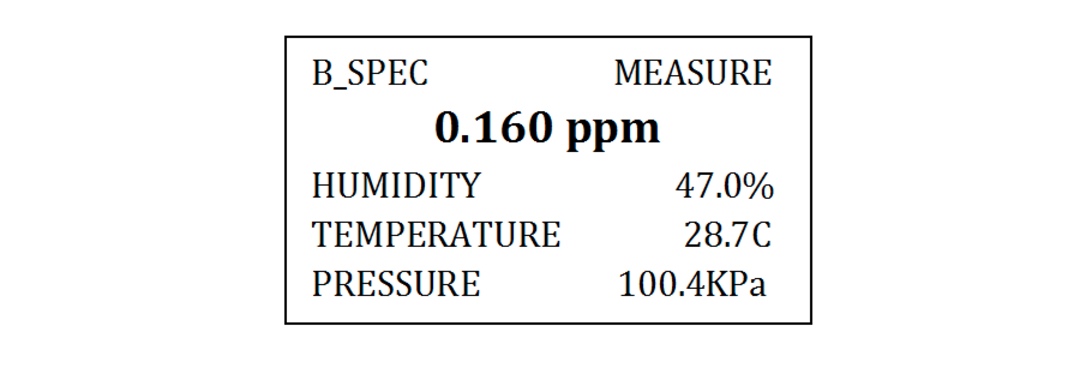
When the F-900 has PolarCept turned on, the Monitor Mode display top line will indicate B_SPEC, meaning that Chamber In is enabled in Special mode. Next, the current state (measure or cleaning) will be shown. If the F-900 is in a state of Measure, the data will reflect the current measurement. If the F-900 is in a state of Cleaning, “Clean” is shown in the upper right corner of the display.
The F-900 has two hydrophobic filters in-line with the internal tubing. This is to protect the F-900 in case any water is sucked into the instrument when using PolarCept. To avoid drawing water into the internal tubing of the F-900 when using PolarCept:
- Fill conditioning Chamber In only to the fill line and never completely fill the conditioning chamber with water.
- Always keep the top panel of the F-900 facing up and do not tilt the instrument when there is water in the conditioning chamber. When water in Chamber In, do not operate the instrument with the display panel facing upwards.
- Do not transport or tip the F-900 if water or moisture is in Chamber In. Before transport or moving the F-900, Chamber In should be completely dry to prevent even small drops of liquid from entering the unit.
- If the Relative Humidity sensor reads high or a “flow blocked” error appears on the display, open the top panel of the unit and inspect hoses for liquid. If liquid has accumulated at the hydrophobic (blue) filter, it should be disconnected and drained. If liquid has penetrated the hydrophobic filter the unit will need to be serviced to prevent circuit board failure. Contact [email protected] with any questions.
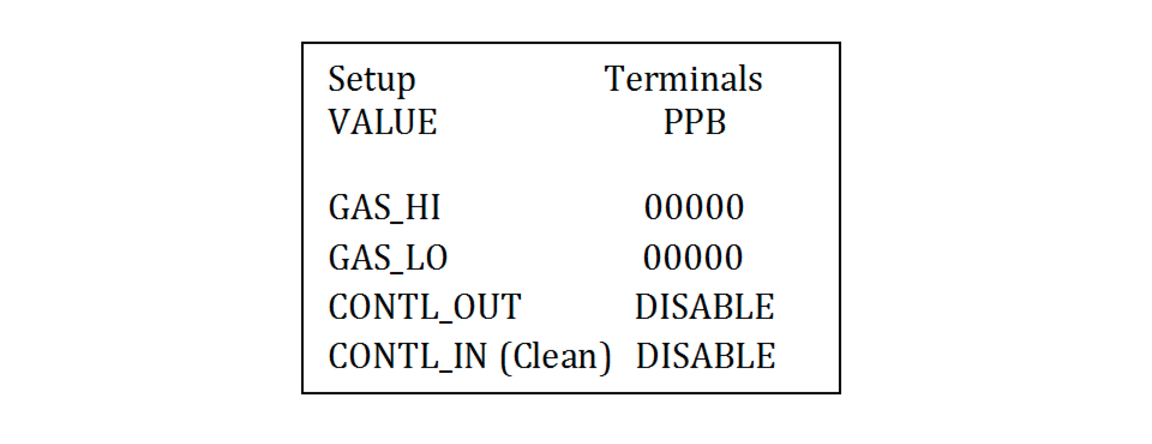
Setup Terminals
The Setup>Terminals Menu is where the F-900 can be setup to have an external fan or gas control connected to the terminal block. The terminal block is located between the chambers for consumables on the back panel of the F-900. The F-900 can turn on and off the gas based on the measured ethylene concentration of the room (or chamber). Other control applications using the terminal block are possible, such as controlling ethylene scrubbers or connection to an external control system.
The F-900 will perform action at the high and low levels, when set. If the concentration of ethylene rises above the Gas_Hi, the gas will be shut off. If the ethylene concentration is lower than the Gas_Lo, the gas will be turned on.
- Press the up/down arrow to switch between parameters.
- Press the right arrow to switch to the column containing the values in ppb (parts per billion).
- Use the up/down arrow keys to set the desired level.
- Press the left arrow or Save to exit back to the Setup Menu. Any changes made will automatically be saved.
- Enabling CONTL_OUT will turn on the standard terminal control, using the output of the pins to control turning on or off the gas and/or the exhaust fan.
- Enabling CONTL_IN (Clean) allows use of the analog input pin to supply a voltage to control the cleaning mode (input signal). This terminal control mode was developed for using the F-900 with other external advanced control systems. When this mode is not being used, set to DISABLE.
- Note: if Setup>Chamber: Chamber In is currently set to Special, enabling CNTL_IN (CLEAN) will overwrite Chamber In to Off.
- Terminal Connections:
- Pin 1: Ground
- Pin 10: Control voltage. Control voltage could be applied during Measure>Monitor Mode to control cleaning mode. Specifically:
- 0.0-1.0V: Cleaning disable (Closed Loop Off, Chamber In Off)
- 1.5-5.0V: Cleaning enable (Closed Loop On, Chamber In On)
To connect a gas control to the terminal block of the F-900, first pull off the removable portion of the terminal block (pull straight out). The piece in the figure below will separate from the F-900. Slide the wire from what is going to be controlled through the opening for the appropriate pin. Use a screw driver to tighten and clamp onto the wire, creating a connection. The removable section of the terminal block is designed to stay with the fan, gas or external control so, if the F-900 needs to be moved, the terminal block can be disconnected easily. The total power draw of the F-900 is .5-1.5 AMP, the max of 1.5 is assuming all sensors are installed and running.
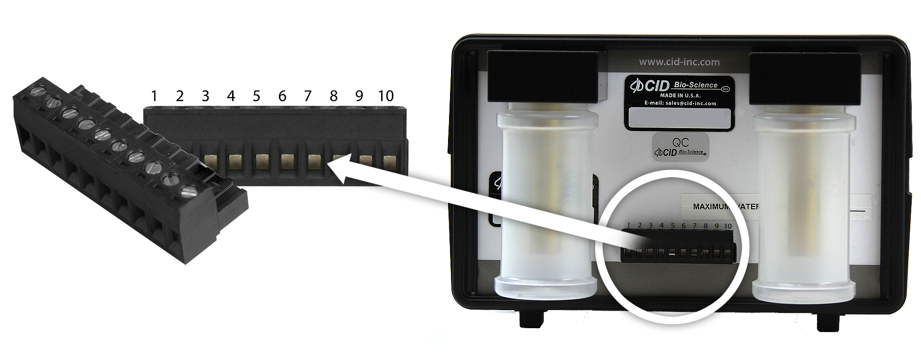
Figure 22: The removable piece of the F-900 terminal block.
Table 3: Designations of the 10 pins of the terminal block (On = 5V; Off = OV):
| PIN | Function |
|---|---|
| 1 | Ground |
| 2 | Current Loop (reserved) |
| 3 | Plus 5 volts (limited through 4.7 ohm resistor) |
| 4 | Gas valve control (C₂H₄): when CONTL_OUT is ENABLE, OFF if C₂H₄ > GAS_HI, ON if C₂H₄ < GAS_LO |
| 5 | Ready signal (5V): ON if during measurement (except correcting offset), OFF otherwise |
| 6 | Alarm or error indicator: ON if one of the following happen: battery low/flow blocked/signal out of range/sensor error, OFF otherwise |
| 7 | CO₂ analog output: 4-20mA for 0 - max CO₂ range (2000ppm or 100%) |
| 8 | C₂H₄ analog output: 4-20mA for 0 - max C₂H₄ range (20ppm or 200ppm) |
| 9 | Analog Input (reserved) |
| 10 | Analog control input for cleaning: use with CONTL_IN enabled |
The digital outputs (4, 5, and 6) can sink up to 45mA to drive an optocoupler. They can only source 0.1mA. Connect the optocoupler photoemitter anode to pin 3 (+5V) and the cathode to the digital output.
Setup Board
The Setup Board Menu should only be changed by a Felix Instruments technician. This menu allows the user the select the type of hardware platform that the unit operates on, and should only be changed at installation, or if hardware is upgraded.
The time interval between cpu/microprocessor calculations reaching the digital to analog converter (DAC) output to pins 7 and 8 on the terminal block is every 200 milliseconds. The internal sensor communicates analog signal to the analog to digital converter (ADC), which then supplies digital output to the microprocessor. The microprocessor then provides digital values for calculated concentrations displayed on the F-900. Those concentrations are then updated (every 200 milliseconds) to a DAC output on the terminal block (for CO₂ and Ethylene).
There is no output for the O₂, but there is for the CO₂ and C₂H₄ sensors.